
Introduction to the C4 model
Published 20 Sept 2025
What you’ll learn
-
The C4 model is a technique to easily visualize software architecture with a set of abstractions and four levels of details at its core, with simple semantics for consistency that everyone understands.
-
Gives the benefits of improved communication, shorter onboarding in projects, faster and safer design decisions with enhanced cross-team alignment that makes staff enjoy their work.
-
Best impact in teams with an optimal combination of method, tooling and knowledge.
Content
- What is the C4 model
- Why the C4 model makes a difference
- Core principles of the C4 model
- Where to start then
- The future of the C4 model
Prologue
You're staring at a blank screen or a clean whiteboard, the task laid out before you: design the architecture for a new system feature, or perhaps make sense of a complex existing one by documenting its structure. Instead of feeling ready to build, a wave of familiar anxieties washes over you, stemming from past frustrations.
Where to begin capture this complexity?
What is the right way to visualize it?
What constitutes good architecture documentation that others can actually use?
What level is correct for this purpose, is this enough detail or am I over-engineering it?
And the most persistent dread:
Will I spend hours or days wrestling with this, creating something that quickly becomes outdated, that nobody ever looks at and that ultimately has no real purpose or value beyond just “having documentation”?
This internal struggle highlights a core truth. Many of us grapple with a lack of a common, consistent language for describing software systems, leading to documentation efforts that feel daunting, uncertain and is potentially wasted. We need an approach that simplifies the process, ensures clarity and relevance and provides diagrams that are genuinely useful tools for communication and understanding, right from the moment we start thinking about the design.
What is the C4 model?
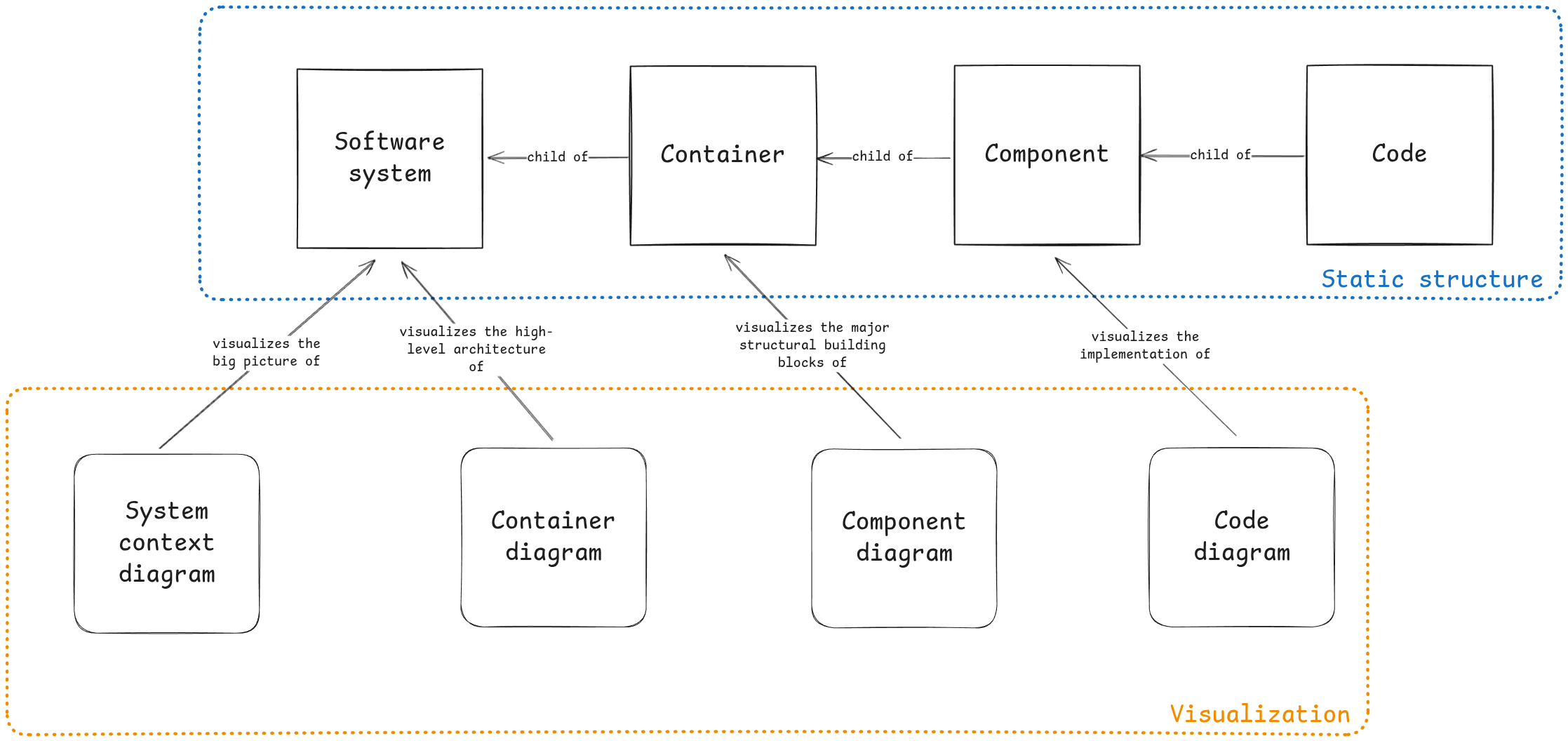
To tackle the challenges of visualizing and communicating complex software systems effectively, we need a clear, common language. That's precisely what the C4 model provides. Developed by Simon Brown, this lightweight method describes the static structure of a software system through a set of four diagrams. The power of C4 lies in the hierarchical nature. It defines your system at different levels of abstraction, allowing you to zoom in and out like a map to show the relevant details for different audiences.
Simon sought an optimal balance that provided just enough detail without being overwhelming. Traditional methods were either too complex (like UML's 800-page specifications) or too vague (like inconsistent whiteboard sketches). So inspired by the 4+1 architectural view model, he created the C4 model to bridge the communication gap in software architecture.
The C4 model primarily focuses on a static structure that describes how abstractions (called systems, containers, components and code) relate to each other. This description of the static structure defines the core of the software architecture model. It moves beyond informal "boxes and lines" by providing a structured framework that clarifies how abstractions fit together, making it easier to understand the overall architecture.
The C4 model helps you decide what to document and at what level, promoting clarity and a shared understanding. Its purpose is to make documentation useful and valuable to the reader, helping you focus on communication rather than documenting for documentation's sake. Less but accurate documentation is better than having a lot that is invalid or outdated. The C4 model makes it easy to start with something at any level and add more as you progress. While the core C4 diagrams focus on static structure, the model is designed to be extended. Once this static structure is understood, it's easy to supplement it with other information. You can add other diagram types to illustrate different aspects of the system when needed, e.g. infrastructure, deployment and sequence diagrams.

Let’s explore the four abstraction levels of details to describe the architecture of a system.
System context diagram
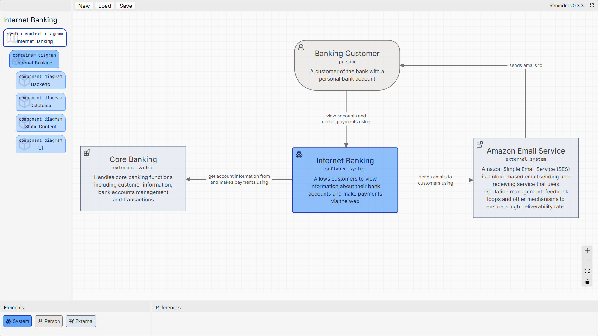
This is the highest, most abstract view of a software system, presented as a black box within its environment. It's designed to provide a clear, uncomplicated starting point for any architectural discussion.
It shall establish the system's scope and boundaries and answer the fundamental questions of what this system is, who and what it interact with and what its key responsibilities are at a glance. It provides the big picture, showing how the system fits into the wider landscape and connects to persons and other systems without getting bogged down in any technical or implementation details.
This diagram is useful for everyone. From non-technical business stakeholders, product managers and executives to the entire technical team (architects, developers, testers) and is valuable for creating a shared understanding.
For a non-technical audience, it offers a jargon-free and concise overview of the system's scope. The system’s place and purpose in the world, how it serves users and collaborators.
For the technical team, it is the perfect starting point to frame a technical discussion to onboard new members and agree on the system's boundaries and external dependencies before diving into deeper levels of detail.
Abstractions
Simplicity is key at this level, to show how this system is positioned relative to its users and ecosystem. There are only three types of abstractions used here.
Software system
Your entire software system is shown as a single, central box. It is treated as a black box to deliberately hide all internal complexity. The goal is to focus on its role as a whole, not its internal parts.
Person
These are the human users (often called "actors") who interact with the system, such as a "Customer" or an "Administrator". This clarifies who the system is built for, usually a role.
External systems
These are all the other software systems that your system interacts with, such as a third-party payment gateway, a corporate single sign-on service or a legacy mainframe. This clarifies external dependencies that are outside of your control.
Relationships
The relationships in this diagram are high-level interactions, not specific technical calls. Each connecting line should represent a flow of information or intent, clearly labeled with a simple description. E.g. "sends email notifications using" an external email service or "retrieves user profile from" a legacy system.
The goal here is to describe the value exchange between systems and users, establishing dependencies without detailing the underlying technology.
Container diagram
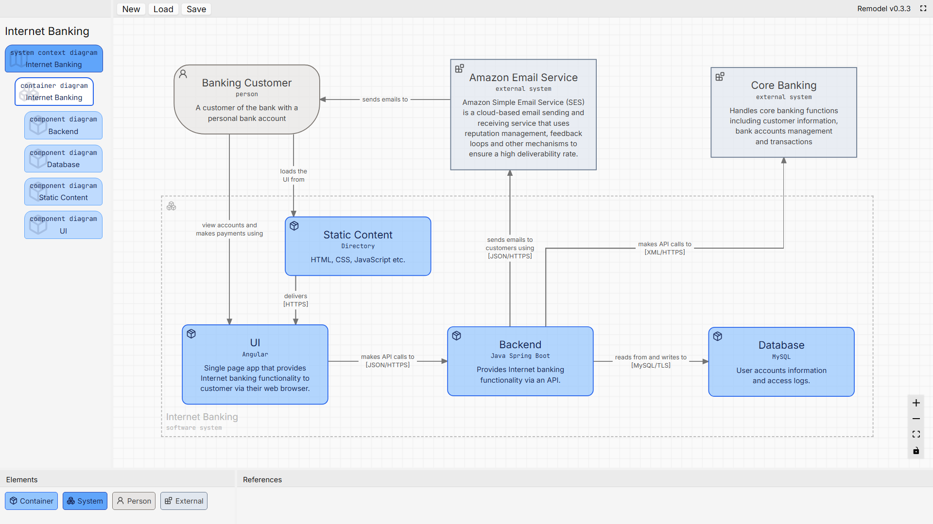
This diagram zooms into the system's internal structure, revealing the major deployable/runnable components (containers) that collaborate to deliver the system's functionality.
It bridges the gap between abstract context and technical implementation. How the system is architecturally decomposed into high-level functional units and how they interact by answering what the major executable components are, how they communicate to fulfill system goals and which technologies or platforms host the key functionality to show the distributed responsibilities between the containers.
The primary audience for container diagram is the tech team. It can be very useful to discuss and discover integration patterns, potential bottlenecks, failure points and technology compatibility between major building blocks.
Software architects can evaluate structural integrity and technology fit. Developers will understand component boundaries and interfaces and DevOps can plan deployment topology and resource allocation.
The purpose is to exposes architectural decisions and technology responsibilities, identifies modularity and decoupling opportunities and enabling infrastructure scoping. It can serve as a roadmap for detailed design.
Abstractions
Highlights how persons, containers and external systems interacts, e.g. how a customer use an application.
Person
The user of an application or deployable unit. To express who is using what and how they directly interacts with it. This clarifies a more specific role for whom the applications of the system is built for.
Container
The executable/deployable units that run as independent processes or services and encapsulate cohesive sets of functionality or data storage responsibilities. This shall be technology specific.
External systems
These are all the other software systems that your system interacts with, such as a third-party payment gateway, a corporate single sign-on service or a legacy mainframe. This clarifies external dependencies that are outside of your control.
Relationships
The focus here is the inter-process communication (IPC) between containers and with persons (actors) and external systems, using labels that describe the high-level intent or data being exchanged. I.e. is more specific than System Context Diagram "interacts with" but less specific than Component Diagram’s method calls.
It could be useful to use a notation of the relation to distinguish synchronous (request and response) from asynchronous (message based) communication.
Component diagram
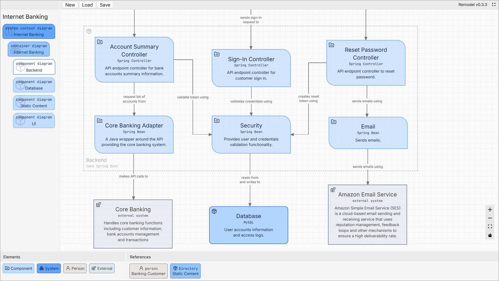
This diagram zooms into a single container to show the individual components it is composed of. It reveals the internal software design and logical structure of a specific part of the system by answering the question of how this application or service is actually built on the inside.
The purpose of a component diagram is to decompose a container into its key logical building blocks and their interactions. It serves as a detailed blueprint for the implementation team, mapping out the major modules of cohesive code and responsibilities as components.
As a feature is the entire process the user experiences, the components are the internal, specialized modules that work together to deliver this feature.
This diagram is instrumental for discussing code organization, identifying areas for refactoring and providing clarity on how different parts of the codebase fit together to fulfill the container's purpose.
The audience for this abstraction level is narrow and highly technical, primarily developers responsible for building or maintaining that specific container. It provides a shared understanding of the internal design and acting as a crucial tool for collaborative implementation and for onboarding new team members to a specific part of the project.
Software developers use this as a map of the codebase to help them navigate the code's structure, understand where to add new functionality, see the impact of changes and effectively collaborate on the internal design.
Software architects review the detailed design of critical or complex containers, ensuring the implementation aligns with broader architectural goals and patterns.
Abstractions
This view introduces the component abstraction while showing its relationship to other abstraction elements.
Person
This us the user role or actor who directly triggers the functionality handled by a specific component. Including a person helps to clarify which part of the internal design serves as the immediate entry point for a user's action. This provides a clear "start of the story" for a particular interaction within the container.
Component
This is the core abstraction at this level. A component is a logical grouping of code with related functionality and responsibilities, encapsulated behind a well-defined interface (e.g. a set of classes in an object-oriented language).
Use this abstraction to break down the complexity of a single container into manageable, cohesive and independently understandable pieces.
Container
When shown on a component diagram, a container refers to another separate deployable unit that a component depends on. It represents a dependency that involves leaving the current process boundary to communicate with another major part of your overall system (i.e. application, microservice, database etc).
External systems
An external system on this diagram highlights a dependency on a system that is outside of your control, often owned by a third party or another team. Showing this relation clarifies which internal components have responsibilities that rely on external services, which is crucial for understanding failure points and integration contracts for the developers implementing them.
Relationships
The focus shifts from inter-process communication to the in-process communication between components. These relationships represent the function or method calls that happen within the same process boundary. Labels should be more specific, describing the nature of the interaction, such as "Executes SQL queries against" a database component or "Invokes processPayment method on" a payment component.
The goal is to clarify the precise nature of the collaboration, which is essential for understanding the flow of control and data within the application being built.
Code diagram
This is the deepest, most detailed level of the C4 model that offers a glimpse into the implementation details of an individual component. It is fundamentally different from the other levels because it is entirely optional and does not have a prescribed formal notation. Its purpose is to clarify the design of specific complex areas where the code itself may not be self-explanatory.
The guiding principle for this level is to diagram only when necessary. The primary source of truth should always be the code and teams should strive to write clean and self-documenting code first.
A code diagram is created only for the most critical or complex components where a visual aid can significantly help developers understand intricate logic, a complex data structure or a non-trivial algorithm by answering how this specific component actually is implemented in the code.
This level is intentionally flexible and allows teams to use whatever diagrammatic notation best communicates the implementation detail. This could be:
-
A UML diagram like domain or class diagram, showing the classes, interfaces, fields and methods involved.
-
A sequence diagram illustrating the dynamics and behaviour of a particularly complex interaction between classes involved in a component.
-
An entity-relationship diagram (ERD) detailing the schema of a database that a component manages.
-
An activity diagram to visualize a complex workflow or algorithm.
The choice depends entirely on what needs to be clarified for the software developers who are currently building, maintaining or trying to understand that specific component.
These diagrams are brittle and expensive to keep up-to-date manually due to their high level of detail.
Abstractions
Abstraction elements are the key building blocks of your software and its environment used to represent distinct concepts at different levels of detail. These elements are the vocabulary you use to tell the story of your system's architecture.
The reason for using these specific abstractions is to create a consistent, limited and easy-to-understand set of concepts that can be used across all diagrams. They simplify complex systems by hiding irrelevant implementation specifics while exposing essential structural and behavioral aspects.
Each element type has a consistent visual representation, clear purpose and defined metadata properties which together provide multiple layers of information in a compact, standardized way to ensure clarity and context-appropriate fidelity across diagrams.
Software system
This element is the highest level of abstraction and represents the system you are modeling as a whole. A software system represents a cohesive set of functionality delivering value to users. It is the central abstraction in level 1 (system context) diagrams and may decompose into containers at level 2.
If your system interacts with other systems that your organization also owns, those can also be modeled as software systems to show a system-of-systems view.

Label
A unique identifier and the name of the software system. It should be a simple, descriptive name that is easily recognizable to both technical and non-technical audiences, a concise business-oriented name reflecting the system’s purpose. Avoid technical jargon.
Role
The role for this abstraction is simply "software system". This explicitly marks it as a top-level boundary, distinguishing it from external third-party systems or other types of abstractions.
Optional categorization for systems with similar functions. Clarifies architectural grouping when multiple systems interact. This is not a substitute for the label.
Default value: software system
Description
The description should provide a high-level summary of the system's purpose and scope and should answer what this system's primary responsibility is in the business domain. This text should be concise and easily understood by anyone, regardless of their technical background.
High-level responsibilities, key capabilities and business goals. Avoid using technical implementation details here such as languages and frameworks.
Person
A person represents a human user of your software system. Also known as actor. It is a role or a persona, not a specific individual. This abstraction is critical for showing who interacts with your system and why.
Can show interaction relations with software system, containers or specific part of containers (components). Could be e.g. end-users, guests, managers, administrators, external stakeholders and similar.

Label
The label is the unique identifier and the name of the user role. It should be based on the role they perform in relation to the system, not personal identifiers. Pluralize for groups.
Role
The role for this abstraction should always be person. This clearly identifies it as a human actor in the system's context.
Default value: person
Description
The description should briefly outline the person's goals and what they need to do with the system. Goals, tasks or constraints. Could be described with demographics or regulatory context and similar.
It can summarize their key interactions or the value they get from the system. E.g. "A customer of the bank who wishes to manage their own bank accounts online."
External System
An external system represents another software system that your system interacts with but is outside of your control. This is typically a third-party service, API or a legacy system that your team does not own or a system controlled by another team.

Label
A unique identifier and the name of the external system. Use the vendor or system name if well-known, otherwise a functional descriptor. The name should be what the system is commonly known as.
Role
The role for this abstraction is external system. This clearly communicates that it is a dependency that lies outside your system's boundary and is likely owned by another team or a third-party vendor.
Default value: external system
Description
The description should explain the purpose of the dependency. It should clarify what your system uses the external system for. Services consumed and interaction constraints. Could include protocols or compliance needs etc.
Container
A container represents a single deployable or runnable unit within your software system, hosting code or data. It could be a web application, desktop app, mobile app, microservice, database schema or a serverless function.

Label
A unique identifier and the name of the container, which should describe its primary responsibility.
Role
The role for a container is where you specify the technical responsibility or level, e.g. database, web frontend, backend service, cache, message broker, microservice. This describes how the container is implemented to guide infrastructure planning and ownership.
Description
Key responsibilities, data handled and scalability or security traits. The description should summarize the container's responsibilities in more detail and can include information about key architectural decisions or patterns used, e.g. "Provides internet banking functionality to customers via a responsive web interface. Built using Angular." Avoid component level logic.
Component
A component is a logical grouping of related code that has a specific responsibility within a container. It is not a separately deployable unit itself but an implementation-level building block. Several components will work together to deliver a single feature.

Label
A unique identifier and the logical name of the component, which should reflect its specific responsibility within its parent container.
Role
The role for a component specifies its implementation pattern or stereotype. This clarifies how the component fits into the container's internal architecture. Examples include "Spring Bean", "React Component", "MVC Controller" or "JPA Repository".
Description
The description should detail the component's specific responsibilities and answer what does this piece of code do. It can also include details about the specific technologies or libraries used if they are significant.
Code Element
A code element is the lowest and most granular level of abstraction, representing individual code artifacts like a class, interface, function or database table. This abstraction is used sparingly and only when the code itself is not clear enough. The C4 model does not prescribe a strict format for this element; its representation is left to the team to decide based on what needs to be communicated, explained or clarified.
Relationships
If the abstraction elements are the nouns of your architectural diagrams, then the relationships are the verbs. They are the connective tissue that brings the static structure to life by showing how these elements interact. A relationship indicates a dependency or a flow of information between two elements. The clarity and simplicity of these relationships are just as important as the elements they connect.
A relationship is always represented as a unidirectional arrow, showing the direction of the interaction. This is crucial as it answers the question of who initiates a connection or who depends on whom. However, the true power lies in how these relationships are described.
The goal is to make the diagrams readable by both technical and non-technical audiences by turning a potentially complex drawing into a series of simple understandable sentences. This is achieved by labeling every relationship with a concise description.
The syntax is designed to form a sentence when read from source to destination:
Source Element + relationship description + Destination Element

For example, if you have a "Customer" (Person) and an "E-commerce Website" (Software System), the relationship should be described so you can read it plainly as “Customer explore and buy products using E-commerce Website”

This simple but powerful convention forces clarity and removes the ambiguity often found in diagrams where lines are unlabeled or simply say "uses."
To make relationships truly informative, the label should contain both the description and the protocol technology. This will then answer both the what and the how.
Important to know though, the protocol technology is optional but could add crucial technical detail, if made without cluttering the diagram. E.g. the technology could be specified in square brackets [] as part of the description.
By adhering to this discipline, relationships move beyond simple lines on a page. They become rich, informative statements that explain both the business and technical nature of the interactions within your system, making your architectural diagrams exceptionally clear and valuable to everyone involved.
Why the C4 model makes a difference
The team and organization will benefit straight away when introducing and using the C4 model for design and documentation by improving communication. But what's more interesting is that this improved communication also brings about positive side effects, providing even greater benefits over time.
Fostering clearer communication and shared understanding
The C4 model provides a common visual language for architecture that improves how software teams communicate.
This consistent understanding helps teams address technical debt and reduce miscommunication that leads to more reliable estimates and smoother development cycles. It's about establishing a clear, common ground that helps teams align faster and work more effectively over time.
Streamlining onboarding and knowledge transfer
With a structured and navigable view of the system's architecture the C4 model significantly reduces the time it takes for new team members to become productive. New hires can quickly understand how different parts connect and function within the system.
This efficient knowledge transfer reduces the burden of bringing new people up to speed, contributing to consistent team productivity and reducing the impact of staff changes.
Supporting confident and pragmatic design decisions
Teams gain better clarity into their system's architecture which supports more confident and informed design decisions. By visualizing system dependencies and relationships, it facilitates practical analysis of various options and their potential impacts.
This foresight helps teams anticipate issues like scalability challenges or performance bottlenecks, leading to more robust designs and fewer costly architectural missteps down the line.
As a result, the team can often discover unknown problems and flaws early in the process by having this ability to communicate abstract design ideas in a clear way.
Ensuring maintainable and relevant architectural documentation
The pragmatic semantics of the C4 model offers a practical approach to keeping architectural documentation accurate and useful. Its structured levels encourage maintaining relevant details as the system evolves, ensuring that the system's blueprint remains a dependable resource.
This ongoing accuracy reduces the cognitive load for developers and provides a clear reference for future development, refactoring and troubleshooting, helping to sustain the system's health and adaptability.
Enhancing cross-team alignment and collaboration
Diverse teams and stakeholders can be better aligned, including development, operations, security and other business roles. By offering shared architectural visualizations that are accessible to everyone, with detail levels for different audiences, it ensures a consistent understanding of the overall system and its connections.
This clarity helps break down silos, improves communication between different groups and roles and supports more cohesive planning across the organization.
Boosting employee well-being and retention
Beyond purely technical gains, the emphasis on clear communication and accessible information has profound positive effects on the work environment itself. When architectural understanding is transparent and easily shared, it significantly reduces common sources of stress, frustration and inefficiency for employees.
This clarity minimizes guesswork and eliminates wasted effort caused by misunderstandings and workday interruptions. It fosters a sense of control and competence. Over time, this leads to a more enjoyable and productive workday that allows employees to focus on meaningful work rather than grappling with ambiguity.
Ultimately, a less stressful and more effective work environment contributes to higher job satisfaction, which helps companies retain their valuable workforce and significantly reduce staff turnover.
Core principles of the C4 model
The most important principles of the C4 model is listed below. The why behind all of them is the driving force of simplicity and communication over completeness and precision.
In essence and one ultimate goal with the C4 model is making software architecture documentation clear, easy to understand and easy to maintain for everyone involved in a software project. It prioritizes practical communication over rigid formality.
Different diagram detail levels for different audiences
This can also be described in short as "use context specific views and abstraction levels".
It fundamentally rejects the idea of a single overwhelming architectural diagram with everything. Instead it champions creating distinct and targeted views that structures architecture documentation through distinct, hierarchical levels of abstraction. Each view is meticulously crafted for a specific audience, from e.g. executives needing a high-level business context view to developers diving into component details, focusing on answering the questions relevant at that level and audience. Think of it like zooming in on a map tailored for different viewers.
This ensures clarity, avoids information overload and makes the documentation immediately relevant and easier to understand and maintain for everyone involved.
Static structure, views and building blocks
The C4 model is primarily concerned with showing the structural building blocks of a system with key elements and their organization, relationships and technologies. The fundamental of "what" and "how” the system is built.
While you can supplement with other types of diagrams (e.g. infrastructure, activity, sequence etc) to show runtime behavior and deployment, the core of C4 itself is structural.
Descriptive, not prescriptive
It is a way to describe and document your architecture, not a methodology for creating it. The C4 model doesn't tell you how to design your system or what those decisions should be, e.g. microservices, monolith, tech choices etc. The architecture knowledge resides with you.
Instead, it provides a clear and consistent framework to communicate the architectural decisions you have made or are evaluating.
Simplicity and communication over completeness and precision
C4 prioritizes clear, understandable communication above exhaustive detail or formal precision. Its diagrams are intentionally simplified, focusing on conveying the essential structural narrative effectively to the intended audience. It's about getting the key insights across quickly and maintainable, not creating a perfectly comprehensive model.
This ensures the diagrams are easy to create, easy to understand and easy to maintain, making them a living and valuable part of the development process
The problem with completeness and precision is high cost of creation and maintainability, difficult to understand and gets rapidly outdated. Because they are hard to create and hard to read, these documents often end up "on the shelf", ignored by the very people they are meant to help.
It’s better with less but accurate documents that are easy to understand than comprehensive but difficult documents that might be invalid or outdated.
The power of optimal relationships
The rule of using only a single relationship line between any two elements is profoundly useful because it elevates the thinking from implementation details to true architectural intent.
This discipline instantly prevents diagrams from degrading into unreadable clutter, ensuring they communicate a clear story. It preserves the diagram's core purpose by answering how the pieces are connected, rather than getting lost in the the granular details of runtime interactions.
This focus on abstracted, high-level connections makes the diagrams more stable and resilient to minor code changes, also ensuring they remain a valuable and long-lasting guide to the system's architecture instead of becoming a fragile and outdated artifact.
Notation agnostic and tool independent
Clarity reigns supreme over rigid diagramming standards. While a simple recommended notation exists, C4 diagrams can be effectively created with whatever works best. A whiteboard, drawing tools or specialized software. The model avoids lock-in, emphasizing accessibility and ease of use.
However, consistency is crucial for effective architectural communication. By defining and following a uniform set of notation and naming conventions, you can significantly improve the clarity and understanding of your C4 diagrams.
Where to start then?
One of the greatest strengths of the C4 model is that you can begin at the level where you have the most urgent need. Usually you start at abstraction level 1 or 2.
System Context Diagram - Sketch out your system as a black box in its environment. Start with the questions like; Who uses it? Which external systems does it talk to?
Container Diagram – View into the major deployable parts like web apps, microservices, databases and start with questions like; How do they collaborate to deliver functionality to the users? What external systems are they accessing?
By starting small you spark team conversations, surface unknown questions and ignite ideas. As you answer those questions by visualizing abstract concerns the architecture naturally emerges in your diagrams.
Tip when starting:
-
Keep it accurate over exhaustive
A few correct, trusted diagrams are far more valuable than many outdated ones. -
Integrate into your process
Embed diagram updates into your definition-of-done and code review checklists. It is important to make diagramming a natural part of the process. -
Don’t over-design
Begin with just enough detail to answer the pressing questions, then iterate.
An intuitive tool like Remodel removes barriers to begin: You can jump right in, experiment playfully and immediately see your changes come to life. That low threshold transforms diagramming from a chore into a collaborative, creative activity that fuels momentum across your project and integrates it as a natural step in the process.
However, truly effective implementation of the C4 model requires more than just understanding its principles and rules. A robust tool becomes indispensable to fully unlock the model's benefits, maintain clarity and consistency across various diagrams and ensure they accurately reflect the system's current state. This elevates the process beyond mere methodology, making it a powerful and practical asset.
The real power comes from combining three essential elements:
Method + Tool + Knowledge = Success
Having the methodology is a great start, but to significantly boost implementation and achieve sustainable success, excellent tooling can drastically improve your ability to efficiently utilize the C4 model and maintain your architecture in real-world scenarios.
While many tools offer some level of C4 model support, they generally fall into two categories. Some like Lucidchart, draw.io, PlantUML, Miro and Visio primarily assist with a predefined notation, using specific shapes, colors and styling. Others such as Structurizr and IcePanel, function as dedicated modeling tools. Among these, Remodel from Optimal Relations stands out as the most recent modeling tool designed for creating software architecture directly in compliance with the C4 model, making the process effortless.
The right tool brings the method to life
The methodology is intentionally notation and tool agnostic. You can absolutely get started with just a whiteboard, pen and paper or your favorite general-purpose diagramming app. There is no lock-in effect and no complex tooling required.
But let’s be honest. Without the right support, good intentions often get lost in daily friction. Over time, even teams who believe in architecture documentation can find it becoming an afterthought, a bottleneck, a burden, fiddly and messy and just damn boring.
To get the best value out of the C4 model, a supporting tool shall make working with your architecture diagrams feel:
-
Clear and structured, with rules that help rather than hinder
-
Fast to update, easy to share and always in sync with reality
-
Collaborative and accessible
-
Lightweight yet powerful with a source of confidence and communication
-
Enjoyable to work with, more like designing and less like documenting
That’s the kind of experience and intention with Remodel. It is designed to make drawing C4 diagrams and adhering to the framework as accessible as possible and make it playful to document software architecture and keep it updated, correct and used as a single source of truth together with the source code.
Depends on your knowledge of architecture
With this said, with the introduction of the C4 model. No method or tool can replace the actual architectural thinking.
Remodel and the C4 model provide the structure and the means but it's your experience, your judgment and your domain knowledge that give the diagrams meaning.
Whether you're designing a new system or documenting an existing one, your understanding of software design patterns, trade-offs and best practices is what makes your architecture effective. They doesn't take over that responsibility, but helps you express it easily.
In other words:
Your knowledge + C4 model + Remodel = architecture that works
While Remodel takes care of the structure and removes friction from the documentation process, it's your insights that turn those diagrams into real value.
The future of the C4 model
As software systems continue to grow in complexity, the need for clear and effective architectural communication will increase. Teams are working across boundaries (technical, organizational and geographic) while building systems that are more distributed, integrated and fast-changing than ever before.
In this environment, it is not enough to rely on tribal knowledge or ad hoc diagrams. Architecture needs to be understood, communicated and maintained by everyone involved in building and evolving a system. This is where the C4 model shines.
Thanks to its simplicity and focus on shared understanding, the C4 model offers a practical alternative to more heavyweight approaches like UML. Where UML often becomes too rigid or dense to be truly helpful, C4 provides just enough structure to support meaningful conversations about design, without getting in the way.
And interest in the C4 model continues to grow. Its creator, Simon Brown, is still actively sharing the model across the world through talks, training sessions and hands-on workshops with companies of all sizes. His continued work reflects a steady and global demand for a better way to communicate architecture in the real world.
From open-source communities to enterprise teams, more and more organizations are adopting C4 as their default approach to architecture diagrams. It is becoming a natural part of modern development culture, especially in teams that value clarity, agility and collaboration.
Looking ahead, the ability to describe systems clearly will only become more important. The C4 model is built for that future. It supports teams in making architecture visible, understandable and relevant - no matter how complex the technology or how fast the change.
If you want an approach to architecture documentation that helps your team stay aligned, move faster and communicate better, then the C4 model is a smart investment for the long run.